Demo

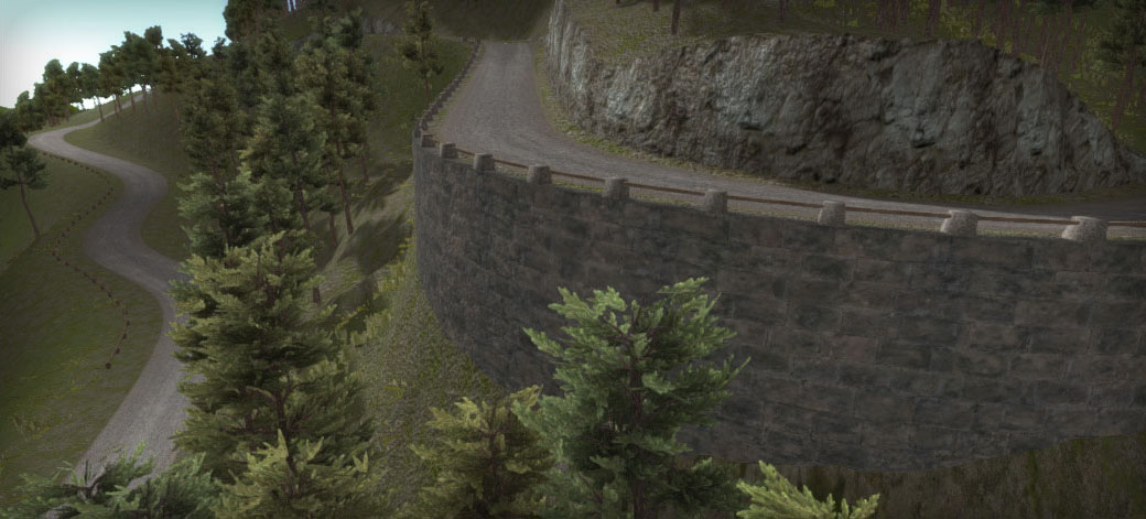
Hilly areas, matching the terrain shape with roads is one of the most challenging aspects of road creation in Unity.
The terrains heightmapscale (heightmap resolution versus terrain size) is an important factor. The higher this value the less control you have over the terrain area near the roads. Within EasyRoads3D this is represented by the Indent values which are customizable but locked to a minimum based on the terrains heightmapscale. The terrain must be leveled at the same height as the road over this Indent distance in order to guarantee the best results.
There are a couple of options you have when you want more detail near the road and you rather not change the heightmapscale of the terrain. This can be achieved in various ways with side objects. For example retaining walls or terrain mesh overlays.
The terrain will still be flattened but in a way that it will not interfere with these objects.
Side Object Setup
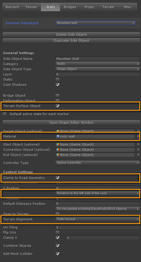
The first thing to do is mark this side object as a Terrain Surface Object. This will auto adjust terrain alignment settings for the affected markers which is covered further below..
This side object generates a wall based on the Shape side object type. The wall shape is defined in the Shape Editor Window, "Open Shape Editor Window" button.
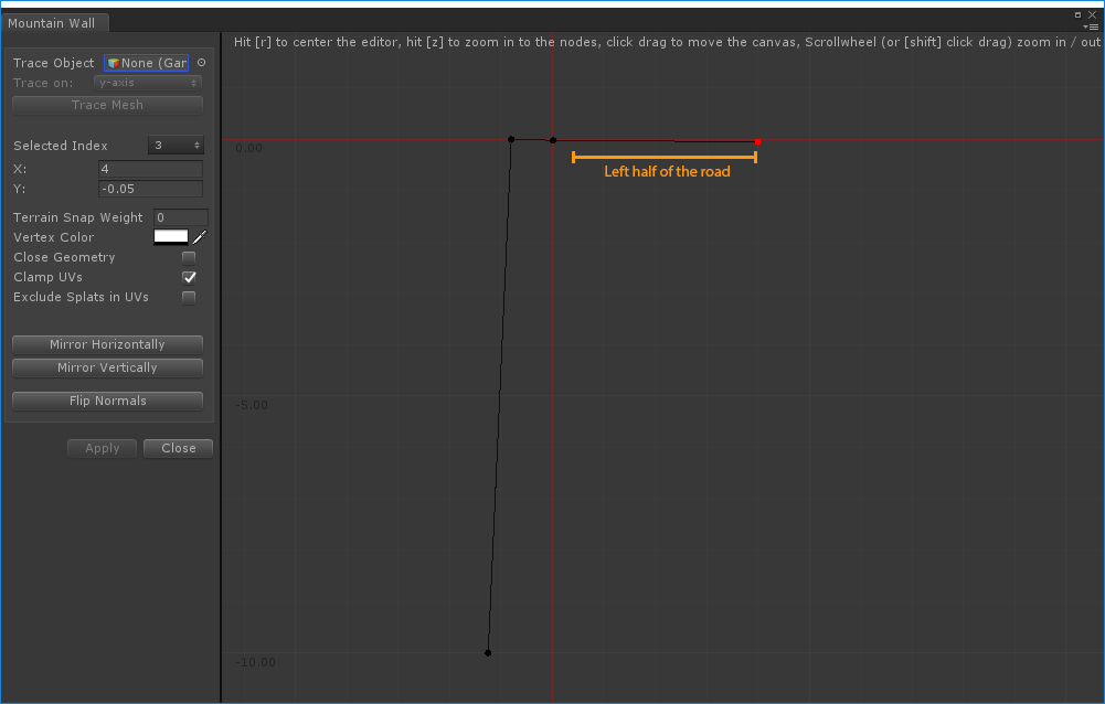
Nodes 2 and 3 cover the area below the road and have negative y values to make sure the road is rendered on top. The reason why the wall side object extends all the way to the right is because the mountain road uses the decal:blend shader, explained here. The shadows projected on the road will actually be the shadows projected on the object below the road. Since the terrain is no longer flattened exactly underneath the road, the shadows on the road will look wrong. Therefore we simply extend the wall side object to cover this area. The shadows on the road will now look the same as projected on the wall.
Also note the vertex colors assigned to node 1 and 2, alpha 1. And the vertex colors assigned to node 2 and 3, alpha 0. This info is used in the shader. Alpha 1 for the wall texture, alpha 0 for the dirt ground texture between the wall and the road.
Because the side object extends underneath the road and we are using a little bit of tilting on the road shape "Terrain Alignment" is set to "Path Normal". The wall will align exactly according the road normal. If you would set this to "None" or "Path Forward" the side object will break through the road.
The guard rail in the above screenshot is an additional side object, "Guard Rail Rock", positioned on top of the wall.
Scene Setup
Using this side object in the scene is fairly simple.
In the main image above the side object is for example activated for the markers 8 up to 12 on the left side of the road.
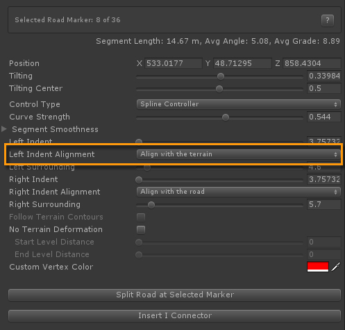
"Left Indent Alignment" is auto set to "Align with the terrain" instead of the default "Align with the road". As mentioned at the start of the tutorial, this will make sure that the terrain is not leveled with the road on that side. The reason why this setting is automatically updated is because we marked this side object as a Terrain Surface Object in the Side Object Manager.
What needs special attention is whether the wall aligns nicely with the terrain at the start and end. Due to the grid nature of the terrain it is very likely that there will be a small gap between the wall and the terrain at the start and end. This can be fixed by tweaking the Start / End offsets for this wall side object on th respective markers. It is recommended to do this in Build Mode with the terrain already adjusted. Changing the Start / End Offsets can be done in the Inspector or in scene view. The H key will display handles that can be used to change the offsets for side objects. To activate the handles make sure to first enter a value other then 0 in the Inspector.
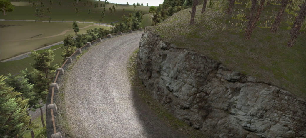
Even with a very small terrain heightmapscale it is impossible to shape the terrain using the terrain object as done on the right side of the road in the above image. What you see is a terrain mesh overlay on top of the terrain object perfectly blending with the terrain itself. This is also generated through the side object system. The material blends a tesselated ground texture, a tesselated rock texture and the terrain splat textures.
Side Object Setup
In this example a terrain mesh overlay is generated with a dirt ground texture near the road, a rock texture for the vertical area, the object is then snapped to the terrain. This area uses the terrain splatmap and textures so it seamlessly blends with the terrain object..
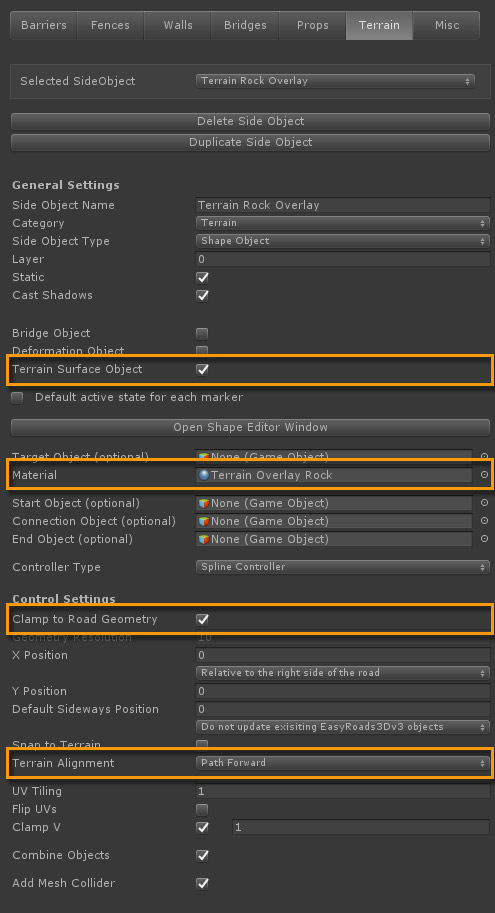
This side object is used on the higher part of the mountain so we do not need adjusted terrain alignment. However, one of the other things "Terrain Surface Object" does is matching the normals of the surface edges with the terrain normals. This is what we want so Terrain Surface Object is toggled on.
Just like in the previous example a Shape Object is used for the side object type.
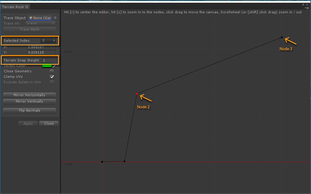
The rock section of the shape follows the original shape of the terrain. This was done by setting "Terrain Snap Weight" for node 2 to 1. All vertices represented by this node will snap to exactly the terrain height at that position.
Since we want the outer part snap to the terrain as well, "Terrain Snap Weight" for node 3 is also set to 1. The x value for node 3 depends on the terrains heightmaps resolution. It should ideally cover at least 1 terrain point, so the distance is at least equal to the heightmapscale (terrain size / heightmap resolution), but probably a little bit more as a safe margin.
Node index 0 and 1 are fully aligned with the road so the snap weight with the terrain is 0.
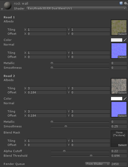
This side object uses the material "Terrain Rock Overlay" with the shader "ER Terrain Mesh Tesselation"
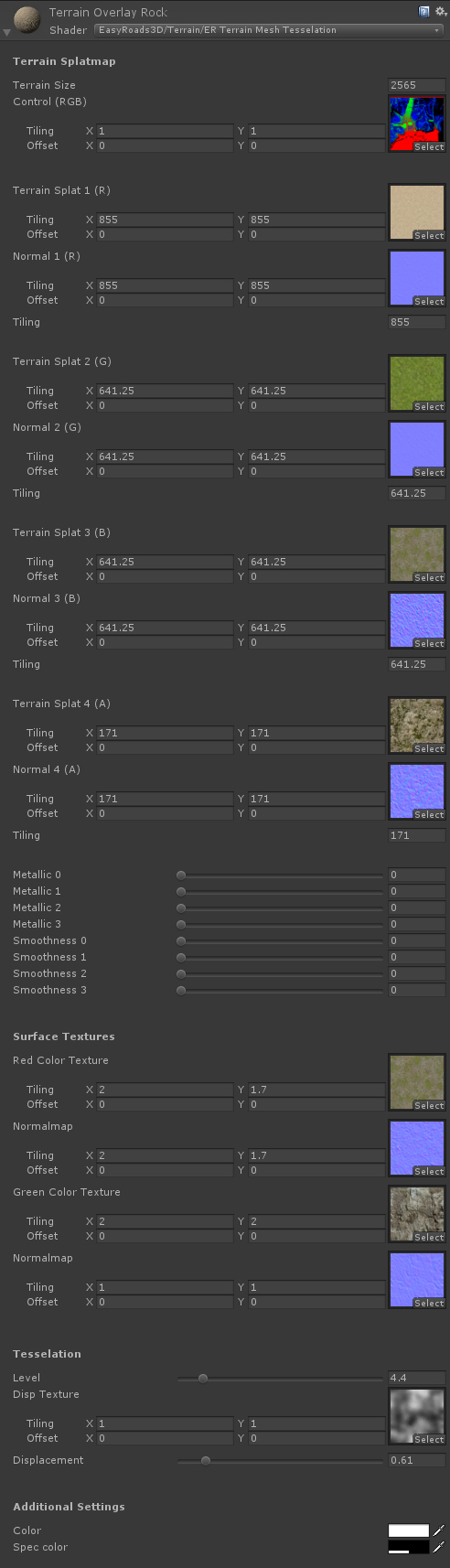
This shader simulates the terrain by using the terrain splatmap as the control map. All terrain textures are assigned. The texture tiling can be calculated: terrain size / the terrain texture size value. We are using one of the Unity tesselation examples shaders here. For this shader we cannot use the uv4 coordinates. So we added additional tiling fields in the Inspector and inside the shader the vertex world position is used relative to the terrain size.
Near the bottom additional texture options are set for the red color channel (the ground dirt next to the road) and the green color channel (the vertical rock segment). The blending strength of the terrain splatmap is controlled by the vertex color alpha value.
All this info can be set in the Shape Editor window. Node index 0 has Vertex Color (255,0,0), assigned fully red with 0 alpha. Node index 1 and 2 have Vertex Color (0,255,0) assigned with 0 alpha, fully green. Node index 3 also has Vertex Color (0,255,0) assigned, fully green but this time with alpha 1.
The result is that the ground dirt texture will blend from the road edge to the rock texture over the horizontal section. The vertical section will be rock texture. After that the rock texture will blend into the terrain splatmap color. This is done over a short distance inside the shader.
In the previous example we used a wall for the lower part. This side object could also be used for a more natural look with more terrain detail near the road.
Scene Setup
Depending on the nature of the terrain setup, this side object may require more steps in scene view.
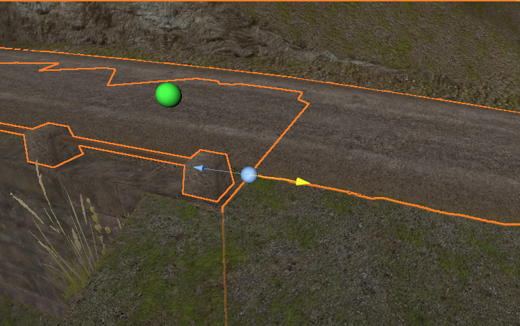
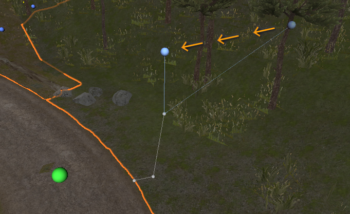
When the terrain area covered by the side object is reasonably flat sideways of the road at the start / end of this side object all should be fine. All nodes snap to the terrain leaving no gap because the terrain is flat. But that is not the case in the main image above (Marker 8 in the demo scene). The current shape will show a clear gap between the terrain and this overlay mesh. Depending on the size, these gaps could be hidden with addional objects or vegetation. In the demo scene this is done to a certain extend with the rocks.
But we also tweaked the shape at the start. This can be done in a similar way as road shape changes (the N key). For side objects the B key toggles on/off shape node position changes. These nodes are displayed relative to the marker position so in the above example we updated the outer node (index 3) at marker 7 by simply moving it horizontally towards the road at about the same position as node index 2, the node that represents the top of the rock section. This way the outer node will gradually move away from the road snapping to the terrain leaving an unnoticeable gap.
Additionally node index 2 for markers 9 and 10 is moved slightly away from the road to make the angle of the rock segment in the bend a little bit less steep.

