Demo

This page covers all side objects used on the race track in the demo project.
Please first review the other side object tutorials as they will explain the various options more in depth.
Because all side objects are only active on specific segments and more often inactive then active, "Default active state for each marker" is switched off for all side objects. This means that these side objects are not generated along the full track. Instead they can be activated for those markers where they should be build.
Since the cam will never get close to the grandstand it doesn't need to be very detailed. There for a shape type of side object is used for the full grandstand. We first created the full shape, this side object is still in the list (Misc > Race Track Grandstand). Because we want a different material for the roof we duplicated the side object twice and named them "Race Track Grandstand Main" and "Race Track Grandstand Roof". For both shapes we deleted the unwanted nodes using the Delete key.
The main grandstand
The roof section
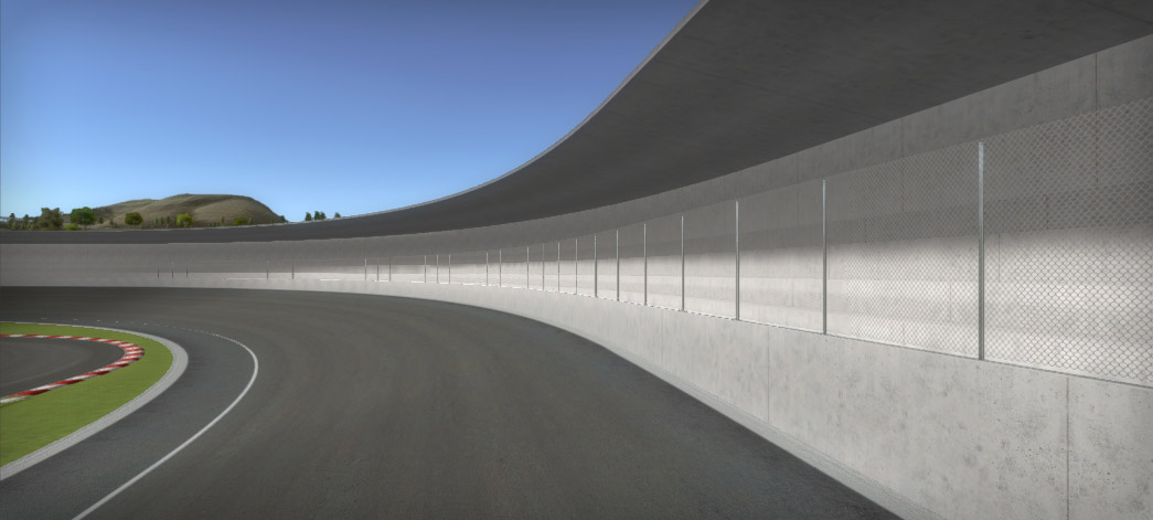
We used Fence (wall fence) for the chainlink fence. This is an example of how you can build side objects at different positions relative to the spline shape..
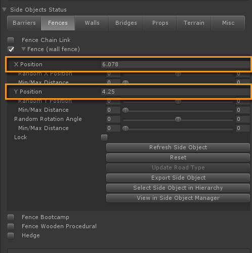
The positioning on top of the wall was done in the side object settings of the selected road. 6.025 for X Position and 4.35 for Y Position.
Instead of using shape type of side objects, the grandstand could also be modeled and imported in the Custom Prefab Editor system. The prefab meshes can have more detail detail like grandstand stairs and entrance / exit areas. The sections in between these objects will inherit the same shape as the outer sides of the meshes, this could be similar as the shape we used..

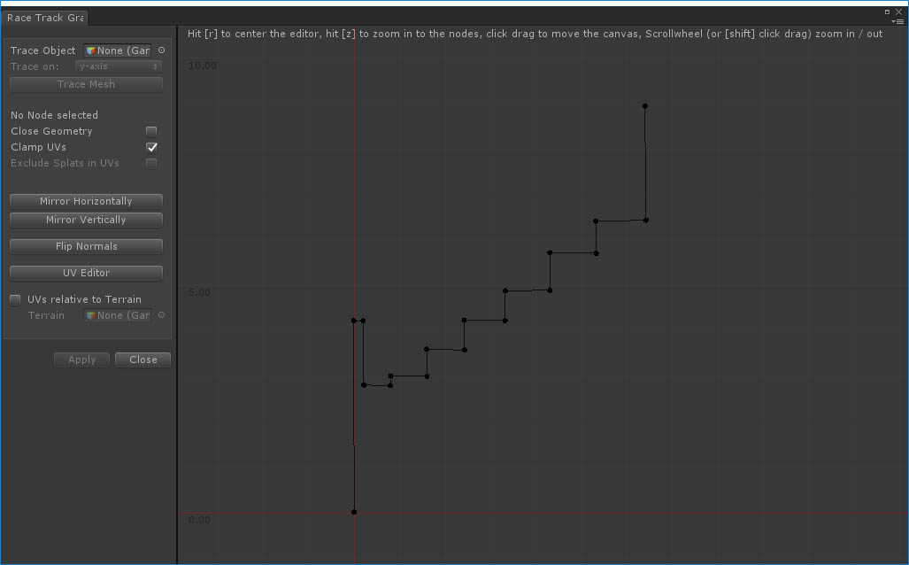
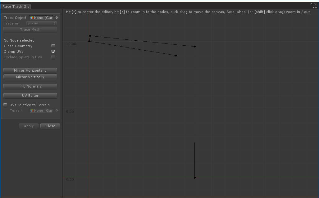
First thoughts would be to use a new road type for the track. But since the terrain is already flat for this area and the track has an irregular shape, we used a shape type of side object:
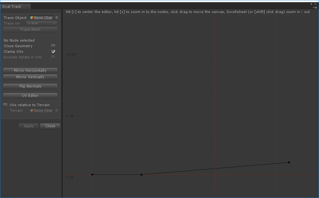
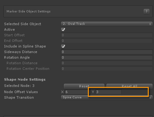
For markers 2, 3, 5 and 6 we raised the outer node (index 2) to increase the banking in the bends. This was done by pressing the B key which toggles on/off node shape position handles for side objects. After selecting the outer node handle in scene view you can either raise the node with the Position gizmo in the scene or manually inside the Inspector by entering the desired Y value.
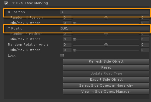
The line marking on the inside where the banking starts could be drawn in the texture. However in this case we use the same race track material as for the kart track. So the lane is done with an additional Shape type of side object with the shape nodes positioned at (-0.15, 0) and (0.15, 0)). The edge between the horizontal section and where the banking starts is at -6 so we set the X Position for this side object at -6, exactly on the edge of the horizontal section. Y Position was set to 0.01 to avoid z-fighting.
The start grid could be modeled and added to the scene manually as it is straight and fairly easy to do. However, if your intention is to build various race tracks and you want to add the start grid markings as decals then you could create a side object for this and reuse it quickly. The source prefab includes the left and right marking.
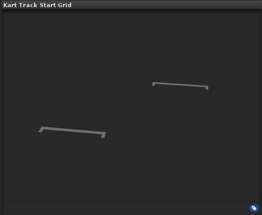
The side object set up is fairly simple. It is instantiated every 6 units (Distance between objects field). The Alignment is set to Path Normal to make sure it alignes with the road also on non flat roads or when banking is involved. "Default active state for each marker" is unchecked since we only want this side object at the start of the track.
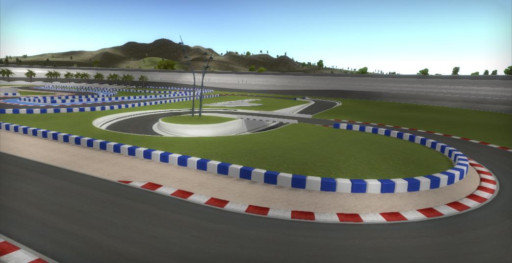
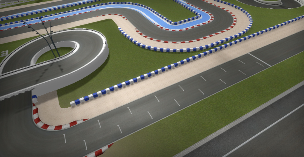
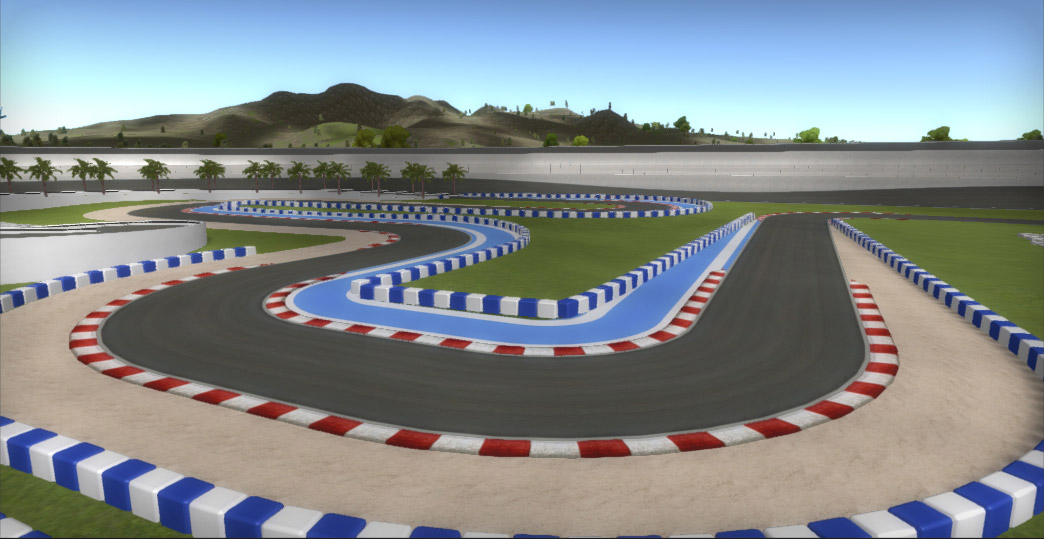
First thoughts would probably be to use the Procedural side object type for this. However, in this example these objects are clamped to the track both at the left and right side of the track. The geometry will be squeezed together on the inside and stretched on the outside in bends. On the inside of the bend, the vertices will be closer then on the outside. The red /white texture pattern will be squeezed / stretched as well because for Procedural side objects the original UVs are used.
So in order to have the curbs look the same on both the left and right side and clamping the curbs to the track, we used the shape type of side object. UVs for shape type of side objects are always calculated based on distance relative to the position on the track. The red / white pattern will look exactly the same on the inner and outer sides of the track.
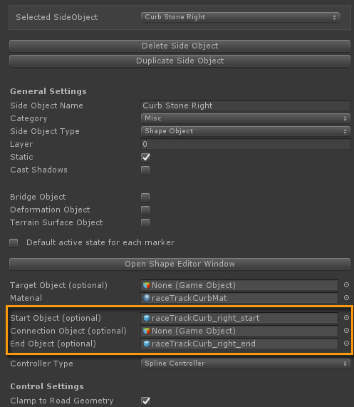
Because we are using the Shape side object type, start / end caps are required to close the gaps at the beginning and end of a curb segment. We modelled the start connection of the curb stone and made sure that the part that will connect to the procedurally generated curb stone shape is exactly at z = 0. That way we can also use it as a Trace Object in the Shape Editor window.

The curb shape visible on the canvas is automatically extracted from the curb model.and will nicely connect with the start object.
We also need an end cap on the right side and we need both versions for the left side as well. This can be done with a small utility that is included in the tool:
Drop the source prefab in the scene (in this case: /Assets/EasyRoads3D/Models/raceTrackCurb): Click "Add Component" in the Inspector followed by: Scripts > EasyRoads3D > ER Mesh Utility
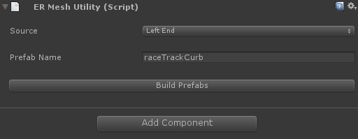
1. Select from the dropdown which version is represented by this version, the object this script is attached to. In this case the end left version.
2. Set a name for this prefab
3. "Build Prefabs" will create and store the prefabs in the same folder as the source prefab
These start / end objects can now be assigned to the respective side objects, "Curb Stone Left" and "Curb Stone Right".
The side object is clamped to the sides of the road. This means it will exactly match the road geometry.
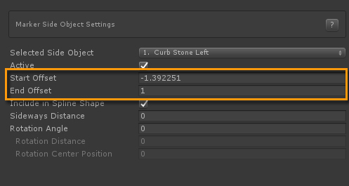
Note that the tricky part here is the alignment of the start / end objects. These start / end objects should be aligned with the track, so the track at that position should be straight. The position can be fine tuned through the start / end offsets in the side object marker settings.
These two side objects are also Shape Objects, simply two nodes, one at (0, 0) and the other depending on the left or right side, at (-5. 0.025). The setup is identical.
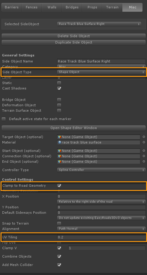
Just like the curb stones these objects should snap to the track so they are clamped to the side of the road.
Also note the UV Tiling field for shape type of side objects. UV Tiling can also be controlled on the material but tweaking it here while preparing / testing the side object might be easier.
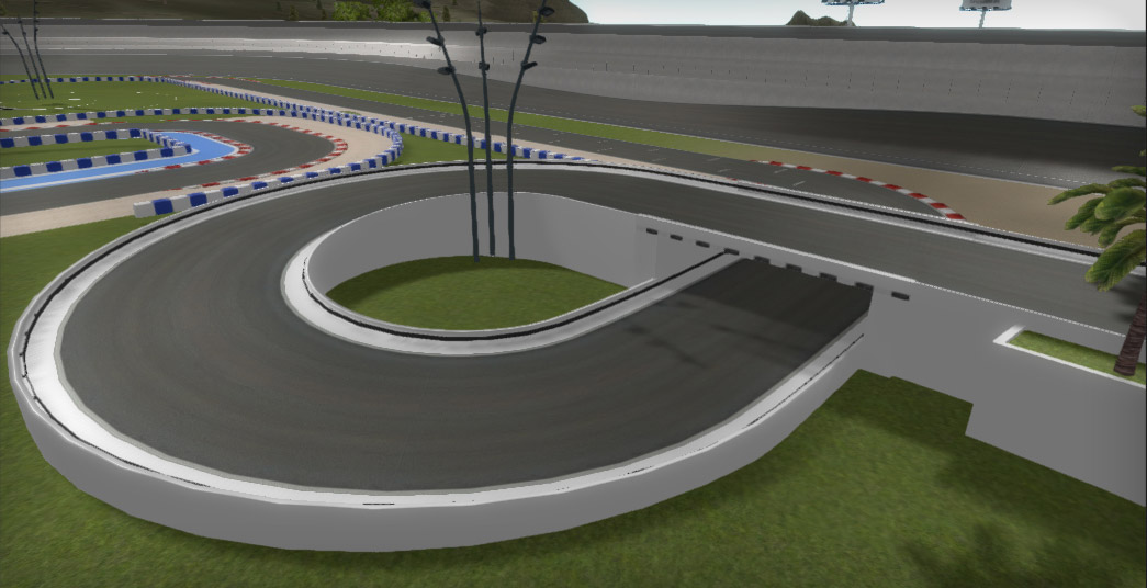
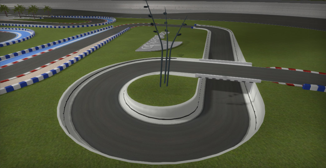
This is the easiest wall type used on the kart track. It is active on the road segment with the bridge on top of the terrain, marker 1 up to marker 5. It is a shape type of side object. The shape is defined in the Shape Editor window.
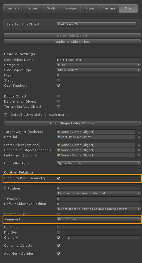
Because the side object continues underneath the road, "Alignment" is set to "Path Normal" that way it will always align with the road and the chances of z-fighting are minimized. "Clamp To Road Geometry" is toggled on for the same reason. This is done because of the relatively sharp circular bend with height differences. By clamping the wall to the road, the geometry almost matches and the chances of z-fighting or geometry poking through each other is minimized.
The previous wall starts and ends at the ground level, at marker 3 it connects with the kart bridge. So that wall type does not require start / end caps, it is eiter aligned with the ground or it is aligned with bridge segments..
The "Kart Track Wall Caps" side object is the lower wall segment with the palm trees. This side object will require caps because it starts later and ends before the bridge object starts at marker 5. That's why a procedural side object type is used with the start / end sections part of the model.
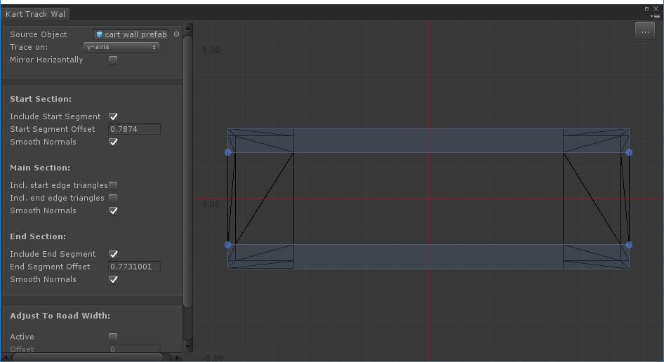
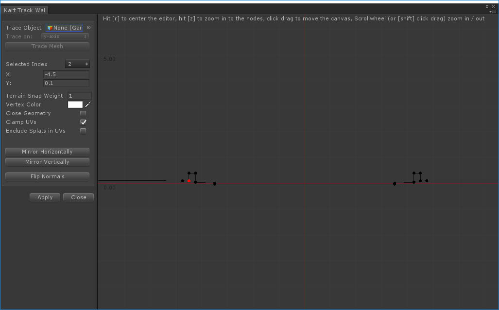
The start / end section blue handles are snapped to the middle section geometry cutting the mesh in a start section, middle section and end section.. This way the start / end sections will only be used at the start, resp. end and the middle section will repeat along the track.
The wall is aligned so the top of the wall is at the same height as the road. The Y position in the Side Object Manager is set to -0.1 to position itjust a little further downwards.
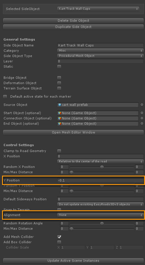
The Alignment for this side object is less crucial. "None" is used because it had the best results at the end but in theory any alingment will do. The geometry will generate slightly different per alignment option but not in a way that it intereferes with other objects.
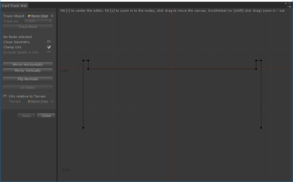
This is the most advanced wall dealing with the situation where a wall moves downwards below the terrain. Since the terrain object is grid based there is no way to have the wall snap in a nice way to the terrain. So the side object also extends outwards at the top over a distance that covers the terrains heightmapscale. That way the terrain can be flattened according the road shape. The gap will be filled with the side object and by using the same grass texture and the same terrain UV coordinates it will perfectly blend with the terrain.

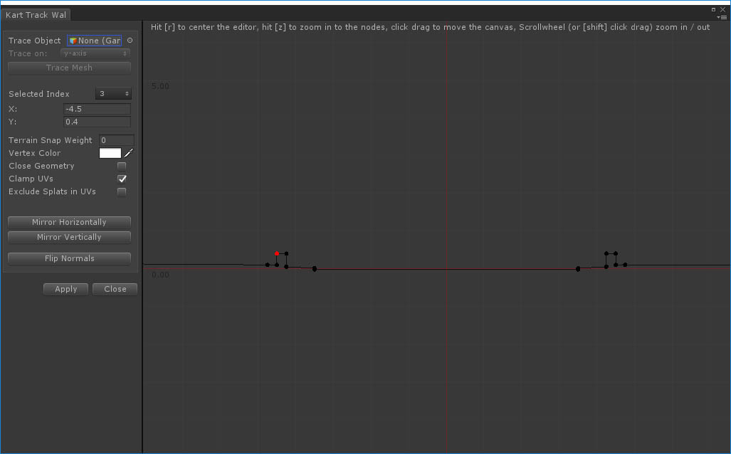
Because nodes will snap to the terrain the Y values of these nodes are less important in the Shape Editor window.Node Indexes 0, 1, 14 and 15. These are the outer nodes that will snap to the terrain. You can select one of them, the terrain snap weight is set to 0.98 and the vertex color is set to white alpha 0. Vertices will be snapped to about the original terrain height and the shaders will render the grass texture. Indexes 1 and 14 represent the vertices where the grass starts next to the white wall.
For the most outer nodes 0 and 15 a snap weight of actually 0.98 is used. A Snap Weight equal or larger then 0.99 on the first or last node means that the vertices will also snap to the adjusted terrain height in Build Mode. This is not what you want for the inner grass island in the circular bend. The terrain will be pushed downwards and level with the kart track, but you do want to keep the grass in the island area at the same height. That is why we used 0.98, that almost perfectly snaps the vertices to the grass as well in Edit Mode and will remain the same in Build Mode. Try setting the Snap Weight to 1 for the most left node and build the track once again. The grass island will not look right.
Node Index 2 and 13. These are also aligned with the original terrain height so the terrain snap weight is 1. These nodes represent the wall element leveled at the same height as the terrain. There for the vertex color is white, alpha 1 resulting in the wall texture being used for this section in the shader..
The remaining node indexes (3 up to 12) are all representing vertices that should be generated relative to the road shape, so Terrain Snap Weight is set to 0. They should all use the wall texture so the alpha value is set to 1.
How to use this in the scene?
You do want to use this type of setup on a reasonably smooth undulated terrain section. On a straight track section this is fairly simple, simply activate this side object for the marker below the terrain and optionally adjust the start / end segments. The results should be fairly good.
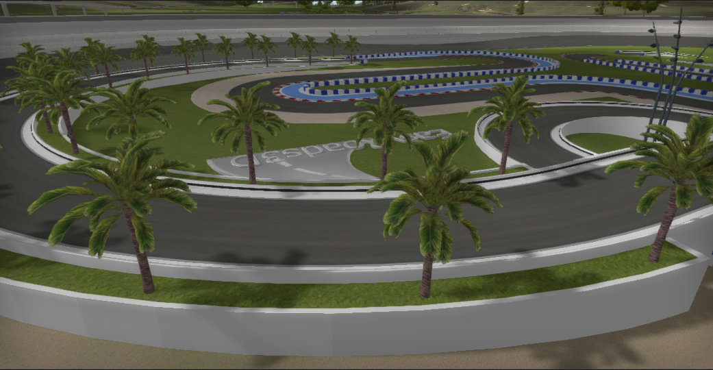
In the demo scene however we used this on a circular segment including a bridge.
The trick here is to first level the terrain height with the height of the upper road crossing the bridge, the road height near marker 6. The outer vertices of the wall side object will all snap to this terrain height. In Build Mode the original terrain will be pushed downwards according the road shape, the road and walls will become visible. The grass texture part of the side object will cover the gap and blend exactly with the terrain grass because the UVs match the terrain UVs on the uv4 channel which is used in the shader.
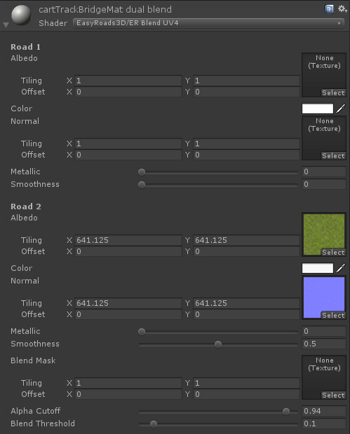
Since the grass texture covers the full area we used the ER Blend UV4 shader. This is an I Connector shader that blends two roads on the main uv channel and uv4. That is exactly what we need here. The Road 1 properties represent the wall area, alpha 0. The race track is not finished yet, for now we simply use color white for the walls. Road 2 represents the grass area. The texture tiling is set to match the terrain grass texture size (terrain size / texture size) which in the case of the demo project means a tile size of 641.25 (2565 terrain size / 4 terrain grass texture size).
Another reason why we used this shader is because it supports setting a Blend Threshold, near the bottom in the above thumbnail..
The low value of 0.1 results in a small edge blend between the wall and the grass.
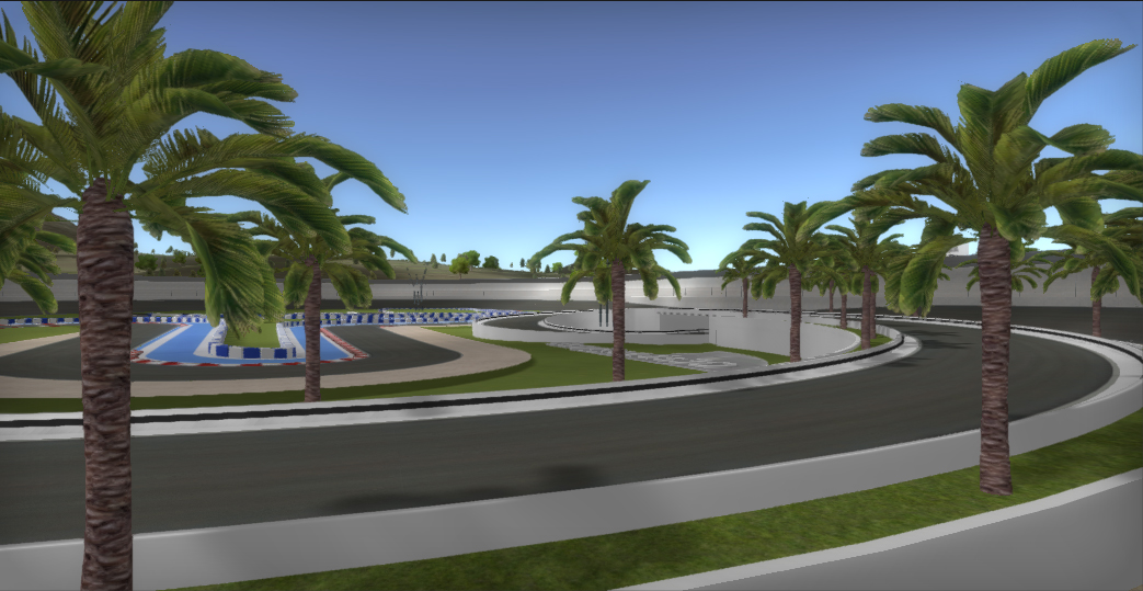
The palm trees in the large circular bend seem not too complicated, something you could do manually or with two separate palm tree objects using the "Palm Trees" side object.
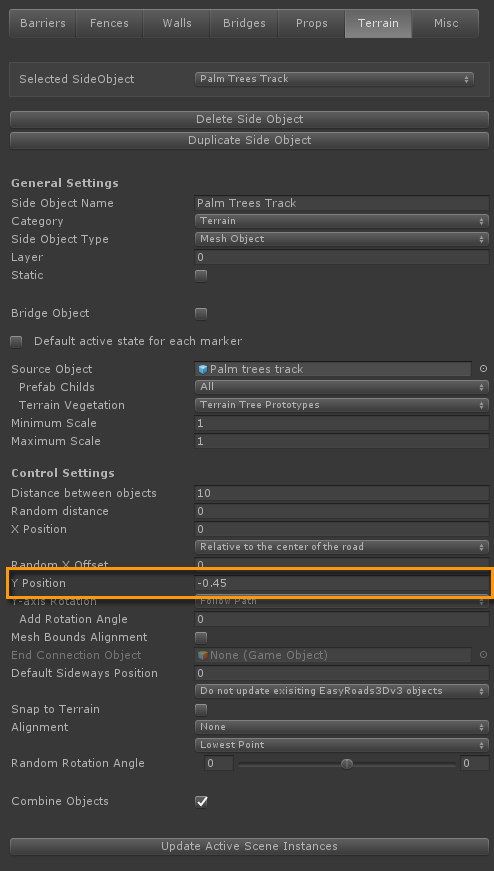
We decided to simply create a new prefab (/Assets/EasyRoads3D/models/Palm trees track). We know the width of the kart track and the walls, so we simply added two palm trees as childs at the correct position, x = -5.75 and x = 5.75.
In the Side Object settings the Y Position alignment is set to -0.45. That way it is nicely aligned with the lower wall.
This is easy and quick to set up and the palm trees will nicely align with the walls. Once you are familiar with creating / dupicating / editing side objects, using this approach is faster then doing this manually. Certainly when this wall setup with palm trees is used in different areas or scenes.

These dark grey barriers should clamp to the wall. The easiest way to set this up is by using a Procedural Mesh Object with Start / End caps connecting with the wall at the beginning resp. end.
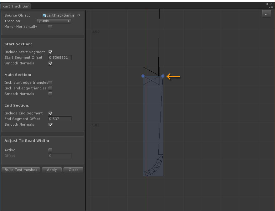
We prepared the source model so that the Start / End offsets in the Shape Editor window can be set in the middle of the side elements that connect with the wall. This is done by creating the triangles of the side elements in a way that they are aligned well with the start / middle / end segment of the main rail geometry. These side elements are cut in half but "glued" together when generating the rail in the scenes. The Start / End gaps will connect well with the middle segments and the higher bottom half will connect with the lower top half for each middle segment.
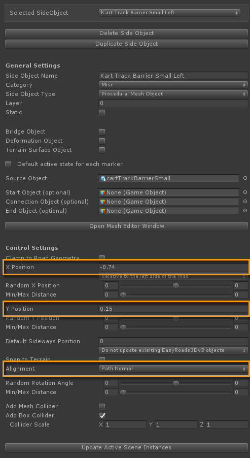
In the Side Object Manager the X Position alignment is set to "Relative to the left side of the road" so the geometry will be created relatively to that side of the road. Because the wall extends a little bit outwards and we want to connect these barriers with this wall, the X Position was fine tuned to -0.74 so the barrier connects with the wall. The Y Position was to 0.15 to raise it a little bit above the track.
Since the Wall side object Alignment is set to "Path Normal" we will use the same setting here. That way it will always align and connect nicely with the wall.
Since the shape can be treated as a box type of shape we use Box Colliders in this case.
Kart Track Barrier Small Right
The left barrier side object was duplicated and renamed to "Kart Track Barrier Small Right".
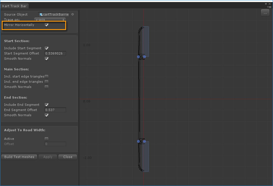
In the Mesh Editor Window "Mirror Horrizontally" is toggled on. That way we can use the same source mesh for the right side.
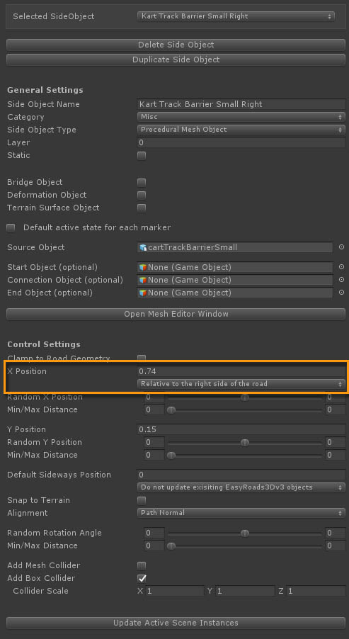
In the Side Object Manager, "Relative to the right side of the road" is selected for the X Position alignment and the negative value -0.74 is changed to 0.74
All other settings are the same
In the scene these small barriers will look better when it start just after the wall starts and ends just before the wall ends. Therefore all start / end offsets were set after first making sure that walls were positioned correctly.
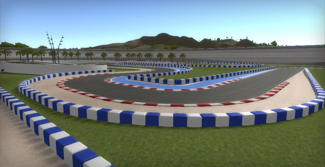
The segments of the blue white barriers should nicely connect therefore a Procedural Mesh Object was used with small Start / End caps
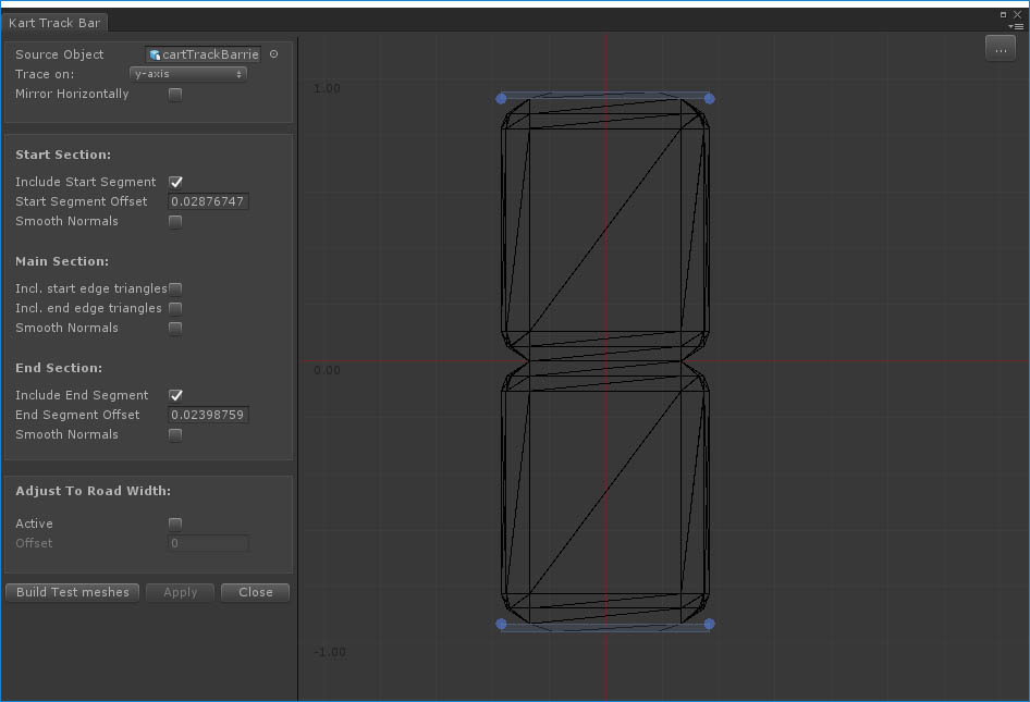
In theory you could skip the Start / End caps and use the source mesh as it is. But the current setup is more clean. The start / end sections will close the barriers at the start and end. The middle section will have less triangles and no invisible triangles.
This side object is only used on objects generated separately along the track. There for the default settings are used with "Default active state for each marker" switched on.
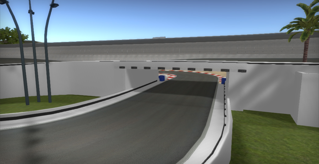
For this particular bridge, a Mesh Object type of bridge could be used. But this time we chose for a Procedural Mesh Object. The advantage of this is that there are no restrictions on the shape of the upper road. The bridge side object will adapt to the road shape while for Mesh Object type of bridges the brdige geometry will not update and instead the road must be aligned with the bridge, usually flat..
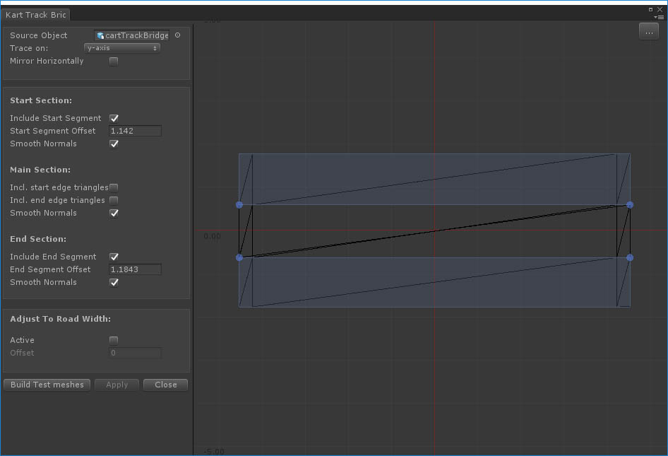
The model is a fairly simple block shaped mesh using slightly wider side walls to connect well with the other walls. Start / End sections are used to close the wall on the inner side bordering the bottom section of the road. That is why the Kart Track Wall side object does not need start / end caps.
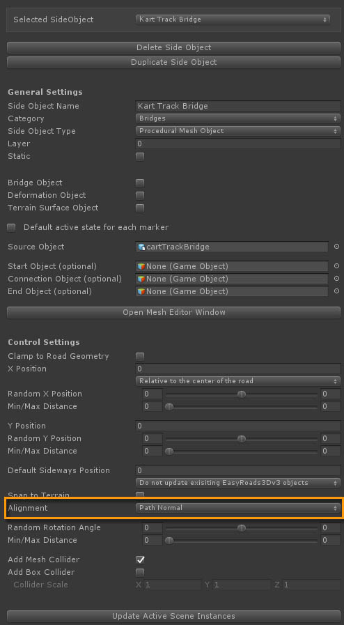
Just like with the other walls you want this wall to use "Path Normal" for Terrain alignment because the race track itself is on top of it. Using "Path Normal" will exactly align it with the road and prevent z-fighting and also bridge elements poking through the road. Apart from that the default settings are used.
The tricky part of using a Procedural Mesh object for this partciular bridge is the alignment of the bridge. The wall side objects are also active on the road underneath the bridge so the bridge should nicely connect to that wall side object. First thing to make sure is that the two roads cross at exactly 90 degrees. You could for example use grid alignment for this.
Once the alignment is correct the bridge start / end offsets can be used to position the bridge correctly relative to the walls on both sides. This too is easie done using grids. The wall side object on the road underneath the bridge is 9m wide. You can set up a grid matching half this size 4.5. That way the upper markers will be positioned at exactly 9m from each other (the width of the wall below the bridge) and markers for the bottom road will snap as well to the grid resulting in a perfect 90 degree angle.
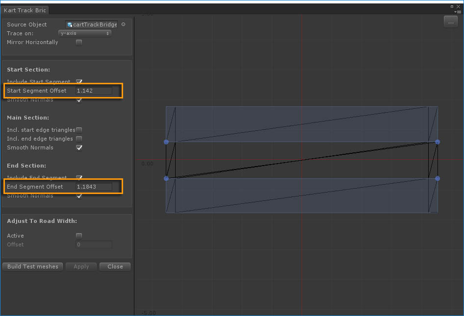
The start / end offsets for the bridge elements are known and available in the Mesh Editor Window. These same offsets can be used to fine tune the position of the bridge. Start offset in the scene is -Start Segment Offset in the Mesh Editor Window. The end offset in the scene is + End Segment Offset in the Mesh Editor Window.
This is one of the more complex ways to use the tool. In V3.x it will be possible to preset start / end offsets in the Side Object Manager which will simplify the above steps. The start / end offsets for each segment on a road will be set automatically.
