
V3.3 beta currently includes the new Flex Connector (intersections supporting non 90 degree angles and different road types), built-in custom road shapes, lane info for traffic AI and a preview of the sidewalk system upgrade and the new multi-lane Road Type Material Creator.
The new shader and Road Type Material Creator options will be further expanded with among others PBR control for line markings, dust level control, shoulder specific noise control and more complex lane specific tyre tracks on intersections and line marking profiles
All known sidewalk triangulation issues have been fixed apart from a small issue visible in the demo scene at the corner on the outside on secondary roads which will be fixed in the next update.
Please let us know if you do see other issues, that would be very much appreciated.
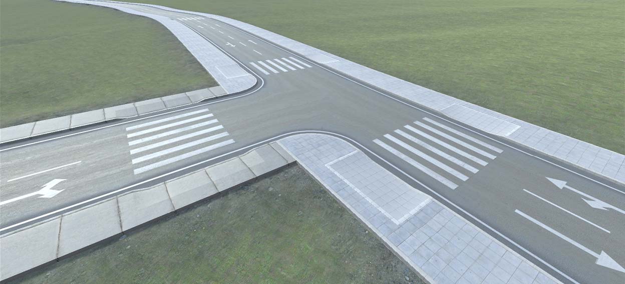
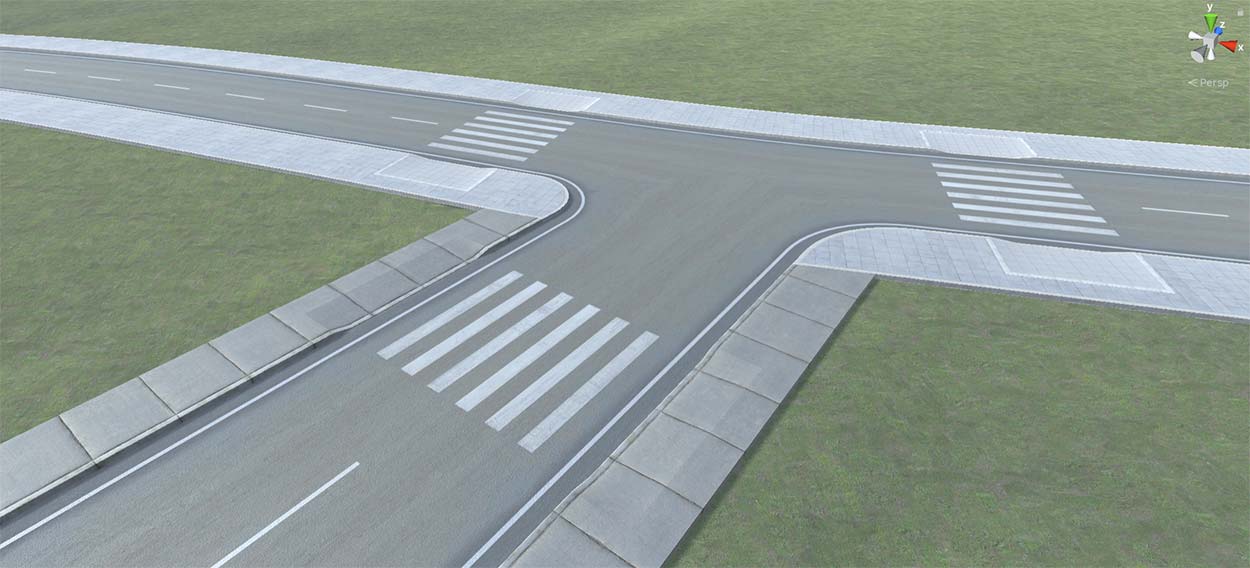
New: Support for diagonal crosswalks on X type of Flex Connectors (upon request). The length of the crosswalk depends on the corner radius, this currently requires a Decal Projector crosswalk preset. Instances of this type of decal preset are dynamically generated supporting different crosswalk lengths
Fixed: Sidewalk triangulation is when crosswalks are active
Fixed: Sidewalk alignment issues when both sidewalk offsets and offsets for secondary roads on the main road are involved
Fixed: Miscellaneous small bugs
Improved: UVs for secondary roads with a a multi-lane material connected to main road sections on Flex Connectors
Improved: sidewalk generation on Flex Connectors when shoulder offset values and or sidewalk offset values are involved
Improved: sidewalk generation on Flex Connectors when sidewalks are not active on both road objects at a corner or when different sidewalk presets are active at a corner
Improved: sidewalk generation on Flex Connectors on corners with sharper road angles
Fixed: beta 16 error when connecting to different road types using standard materials instead of the new multi-lane material
Fixed: Miscellaneous small bugs
New: URP 17 and HDRP 17 support for the new multi-lane materials
New: Preview of the new multi-lane shader for Flex Connectors
Improved: lane data display on I Connectors
Improved: Depending on the original road shape an additional triangle strip is added on Flex Connectors for better UV distribution
Fixed: Miscellaneous small bugs
Preview: Road Type Material Creator including multi-lane visualization matching the road type settings, more info and current limitations
New: "Runtime Road Network Creation" option (General Settings > Project Settings), this is used among others for EasyRoads3D folder structure and project Build optimizations
Improved: Road type Speed Limit on Connectors changes and "Update Scene Instances", this will now automatically update, there will be an alert message for customized speed settings for lane connectors which can optionally be preserved
Improved: New Road Type "Offset for Secondary Roads" option in the "Road Shape" tab, this controls the alignment of secondary roads with the main road on Flex Connectors. This is currently supported for flat Primary road shapes
Fixed: Miscellaneous small bugs
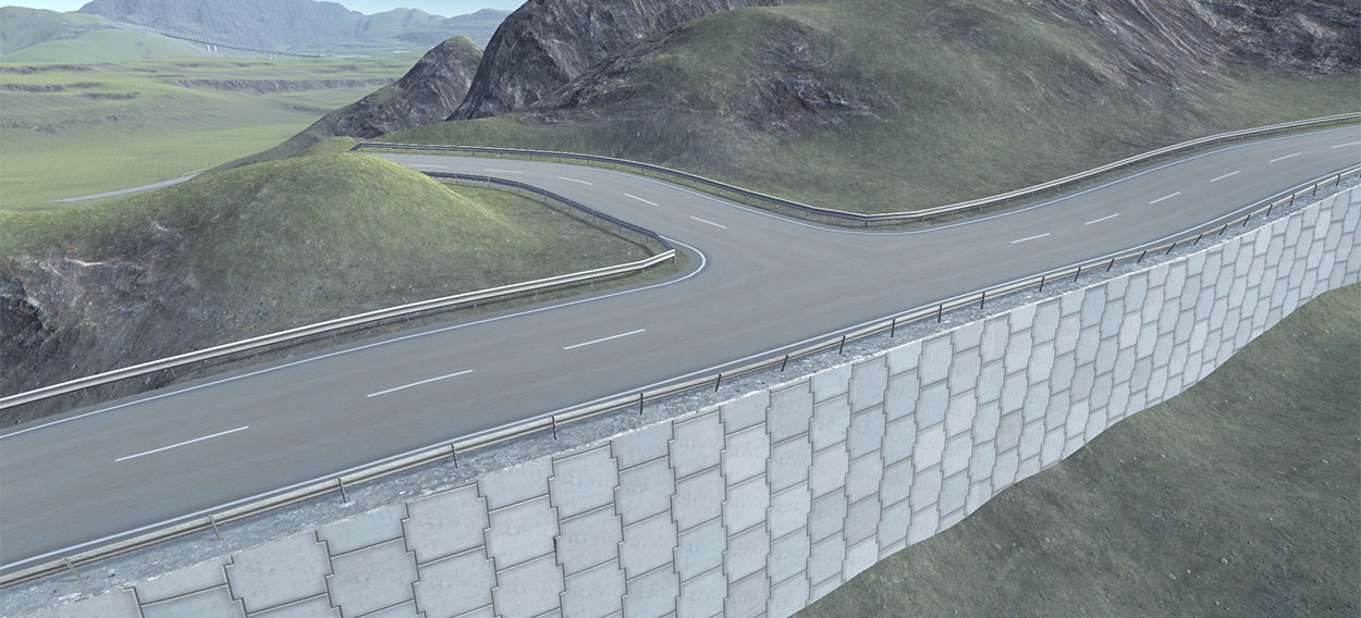
New: Shape type of side objects supporting a triangulation routine for a Dual Sided setup, the left and right side will be connected. It makes it possible to use the Shape type of side object to create for example bridges and overpasses that continue on intersections higher above the terrain
Improved: Secondary road triangulation for wider road types, the connection radius now auto adapts to the main road section angle increasing the available space when stronger angles are involved on the main road
Improved: a value of 0 for Lane Count is now supported for road types, this can be used for road objects where no AI traffic should be generated, no lane connections will be generated on intersections, no need to manually remove lane connections.
Improved: Previously in a situation where both road objects A and B should connect to road object C it could happen that the road objects A and B were merged in one road when these two road objects were also within snapping range. Flex Connector snapping now has priority over merging two road objects in one. So road A will safely connect to road object C and afterwards road object B can connect to the newly inserted Flex Connector
Fixed: Possible duplicated Flex Connectors after attaching a new road object to the connector
Fixed: Main road section radius handles not visible in the Scene View window
Fixed: Miscellaneous small bugs

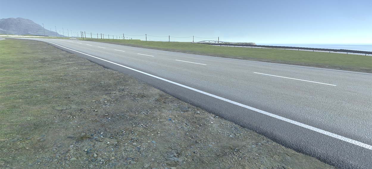
New: Random terrain height offsets relative to the road edge. "Max Height Offset" and "Level Distance" controls in: Road Types > Terrain Control. This is for road types with thickness, see how the terrain height randomly aligns with the road edge in the image.
New: AI Traffic support on I Connectors
Improved: Road Types > Road Type Profile Editor, Inspector / Scene View improvements
Improved: adjusted road widths at v3.2 intersections will auto adjust to the original road type width after conversion to the v3.3 Flex Connector
Improved: 'Static' option for v3.3 sidewalk objects
Fixed: AI Traffic related issues when Left-Hand Traffic is selected
Fixed: Secondary road triangulation issues on Flex Connectors
Fixed: Secondary road Left and Right Corner Curvature values on Flex Connectors not being editable at specific incoming road directions
Fixed: Miscellaneous small bugs
Road types can be managed from the project folder through the new prefab system. The type of road can be set (0.17 in the video). This is used among others on the new Flex Connector to prioritize specific connection layouts. This can also be used for AI purposes.
Four new tabs have been added to the top: Road Shape, Lane Info, Material, Sidewalks.
v3.3 supports custom built-in road shapes on the new Flex Connector (0.25 in video). The shape can be set in the first "Road Shape" tab. Roads with thickness are now also supported for built-in road types. The number of shape nodes can be set, the position of each node can be set both in the Inspector and on the prefab stage. Important here are the Left and Right Edge Offset checkboxes (0.36 in video). These define positions on the road texture where the UVs for the left / right side of the texture should remain at a fixed position from the edge. In the current crossing options this is defined by "Inner Segment Distance" in the Corner / Sidewalk Settings. The generated UV coordinates will result in correct texturing of the road edges on crossing corners. So when using this, first get the total node count required for the road objects and make sure to add two extra nodes to the total road type node count.
In the Lane Info tab (0.52 in video) the number of lanes can be set, based on the number the lane position will be set automatically including whether they are left or right lanes. The positions can be changed manually. Lane info will be used for generating the road material (customizable in the new Road TYpe Material Creator) and for AI lane data.
UV data and material info can be set in the Materials tab. The reason for this new materials tab is the advanced material options in v3.3 supporting customizable lanes. The new Road Type Material Creator can generate the material matching the road type profile.
The Sidewalks tab can be used to set the default sidewalk state for this road type.
Further below in the road type settings the speed limit can be set per road type (1.10 in video), available at runtime through the scripting API.
Starting at 1.20, the above new options are shown for versions older then Unity 2018.3. The Road Shape Editor button (1.31 in video) will open the new toolbar tab similar to the one explained above. Also newis the Visualize Road Type button (1.36 in video). It will show the road type in Scene View.
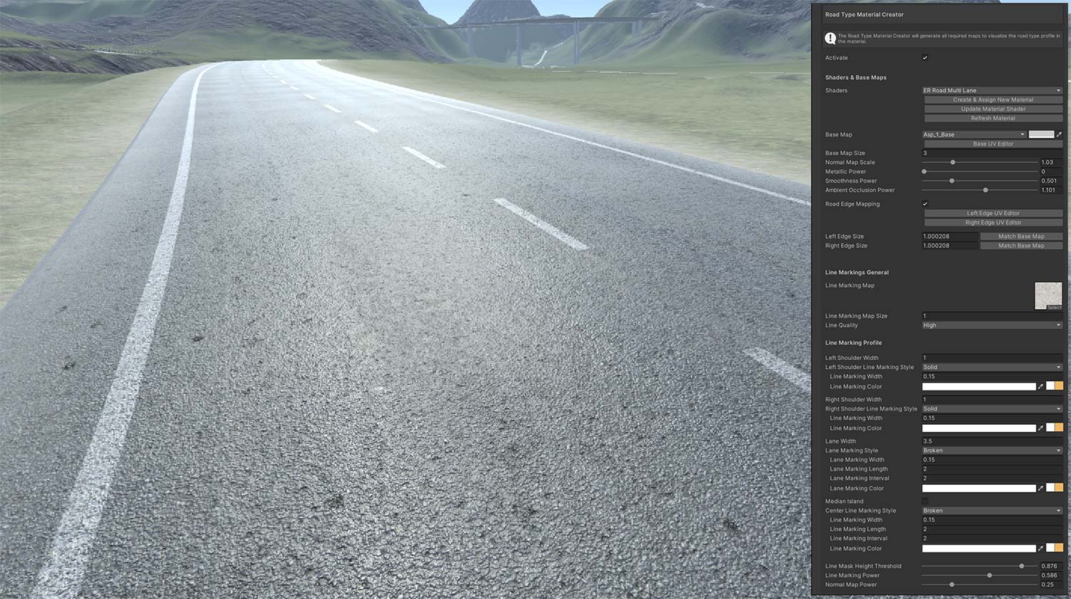
The new Road Type Material Creator is available in the Material tab of the v3.3 "Road Type Profile Editor" in "General Settings > Road Types". When this option is activated the material controls will be visible.
The dynamically generated materials require v3.3 EasyRoads3D shaders. The shaders that support customizable lanes will be visible and selectable in the Shaders dropdown. The beta package includes the new "ER Road Multi Lane" shader.
New materials will be created automatically when for example duplicating a road type and renaming it. It is also possible to create a new material so the material of the original road type does not change.
The starting point of the material is the base texture which will tile according the size setting. The available base textures are located in /Assets/EasyRoads3D/Textures/Roads/BaseMaps/. This includes matching normal maps, PBR related maps and optional noise map masks to control noise on the road shoulders.
By default the base map will tile over the full road width. Optionally road edge detail can be added separately to the base maps. When activating "Road Edge Mapping" additional controls will be available to set the UV coordinates for the respective edge detail on the base map and the edge size. Generally this will be proportional to the main base map UV coordinates and size, "Match Base Map" will calculate that size based on the set UV coordinates.
The left and right shoulder sizes can be set. Important here is the status of "Synch Road Width" in the "Road Shape" tab. When "Synch Road Width" is active the road width will auto update to shoulder size changes, lane size changes and lane count changes. Otherwise the lane size will auto adjust to the road width and the current shoulder sizes.
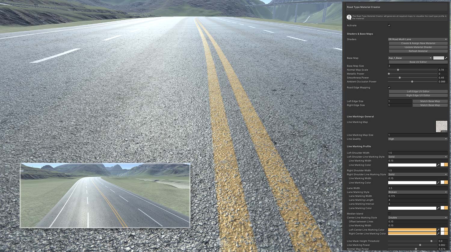
It is possible to set the line marking texture and for each line marking type the color, size and pattern is customizable.
The new shaders include additional controls to blend the line markings with the road, these controls are also available in the Road Type Material Creator Inspector.
Additional controls are available to customize tyre wear and noise. A single noise map can be used or lane specific noise maps can be assigned to add variation in the case of a multi-lane road type. The blend strength and level is customizable.
The new shaders and Road Type Material Creator options will be further expanded with, for example: PBR control for line markings, shoulder specific noise map options, dust level control, etc.
The beta package includes two new road types, the "Primary Road 1 x 1" and "Primary Road 2 x 2" road types with materials created using this new new Road Type Material Creator.
Feedback and road material requests are very welcome and appreciated.
Note:
Most of the Material Creator Inspector controls are delayed float fields. So press the enter key after making changes to update the material.
Current Limitations:
- One way road types are not yet fully supported, lane markings will not be visible
- For lane markings, the "Double" and "Mixed" styles are not supported yet, these styles are supported for the center line markings
- Matching materials for connectors will follow, for now the material can be duplicated and the "Lines"
- URP and HDRP versions will follow
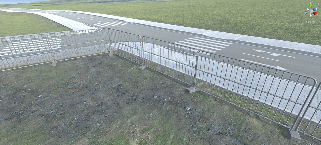
By setting the lane info, the system can auto generate lane direction marking decals on road objects for each lane in v3.3.
Matching decals can be created in the Road Object Decal section in General Settings > Road Types. The new decal option Lane Direction Marking is used for this.
Options are "Straight", this is for the road object itself. At intersections the options are "Straight","Left", "Right", "Straight Left", "Straight Right", "Left Right" and "All Directions". The decal Material can be assigned, the Decal Length (size) of each instance, the Distance between Markings and the Height Offset of the decal relative to the road height. In the UV Editor window the respective decalk arrow can be selected.
Based on the turn directions of the available lane connectors, the corresponding direction marking decals will be selected.
In V3.3 new built-in connections types are introduced starting with the Flex Connector. Currently this is a new connector option for the current X and T Connectors after instantiating them in the scene (2.07 in video). At the moment it is important to first pull out new roads or attach existing roads. After that the Connector can be turned in a Flex Connector (2.21 in video). All connectors will support flexible angles, roads can be detached and attached. Different road type can be selected. As visible in the video at 2.47 this requires road type selection for both the connector segment as the road. The reason for this is that you may want a different surface in between the main road and the connected road. The main road triangulation can be changed (3.07 in video) to match the connected roads, outerline options are currentluy possible through decals (3.22 in video). These decals can be set in the decalk section of the specific road type. Examples will follow in next updates. as can be seen at 4:34 in the video, the number of connections is not limited to 3 or 4, more connections can be added.
Main Connection Decals are road type transition decals that will be generated on Flex Connectors on the main road at the edge where other road objects connect. They can be used to blend the two road materials and visually improve the transition between the two road types. Decal presets can be created per road type in Road Types > Road Type Decals.
These decal options will be available on Flex Connectors when another road type is attached. Multiple decals can be created per road type to match the different road types or to add variation.
The v3.3 beta scene includes two decal presets that can be reviewed.
To create a new decal preset press the "Add New Decal Object" button near the bottom in the Road Types Decals section. Select the "Main Connection Line Marking" decal type from the dropdown, give the new decal a descriptive name and assign the decal material.
Open the UV Editor. The road texture will be visible with an highlighted area. Move / resize this highlighted rectangle to cover the bounds for the new decal on the material / Texture. To make it easier to get accurate results, either enter the values manually by calculating them in your paint program, or temporarily add a thin coloured line at the decal boundaries so the rectangle bounds are clearly highlighted in the texture.
Optionally it is possible to add multiple break points, this will optimize the created decal by clamping the UV coordinates to the nearest break point. The final length of the decal will be calculated accordingly. When adding two or more break points there will be an additional option to set Start / End sections, the first and last break point. This can be used to blend the decal in at the start and out at the end, the middle section will be repeated. The decal examples in the v3.3 beta demo scene use this option. Close the UV Editor window.
The next decal settings in the Inspector are "Decal Width" and "Decal Length". These values can be entered manually, however it is easier and more accurate to press the "Match Main Road Material Tiling" button. Based on the bounds of the highlighted rectangle in the UV Editor and the UV Tiling for the road material the matching decal Width and Length will be calculated.
The decal can be moved sideways "X Offset", by default the center of the decal matches the road edge position. "Height Offset" places the decal higher above the road surface and "Start Offset" resp "End Offset" values can be set to control where the decal should start and end relative to the connected road. By default Start and End sections will be created exactly according the Start and End offset values. When "Interpolate Starte / End sections" is active, these sections will snap to the mid sections. This can be used for road textures with a clear pattern, like paved road textures.
The best way to fine tune these settings is by selecting or creating a Flex Connector where the involved road types are used. First press "Update Scene Instances" near the bottom in the Road Types section.
This decal type is generated relative to the right side of the road. So look in the Inspector at the main road Connection where the secondary road is connected to the right edge of this road object.
For this specific connection the "Main Road Connection Transition" option will be available in the Inspector, all available decal presets will be listed. After selecting the new decal preset that you created, open the foldout. The same decal controls will be visible. The decal will instantly update in the scene after making changes so this is a quick and easy way to fine tune each decal preset. Note that these settings are the main decal preset settings, these settings are not instance specific decal settings for this Flex Connector.
Custom Road shapes for the main connection road type are supported. When moving the X Offset, the decal shape will adjust accordingly.
V3.3 will have new sidewalks options. A new Sidewalks section is added to the General Settings tab. New sidewalk presets can be created here. Two provisional sidewalk presets are provided in the beta package. Currently only the standard shape is supported with optionally the "Outer Curb".
Sidewalk presets can be selected on road objects, road types and on Flex Connectors per connection. So contrary to v3.12 and v3.2, sidewalks can be activated directly on roads. The default sidewalks state can also be set for each road type.
Crosswalks are supported in a way that the pavement at crosswalk positions can be customized. The standard version, the "Concrete" sidewalk example in the beta package, will auto generate the UV coordinates based on the currently set UV coordinates for the sidewalk inner pavement. The second option is to set crosswalk specific UV coordinates. Two types of triangulation are supported, the provided provisional "Tiled Pavement" uses the more complex version with the "Include Outer Strip" option. The Crosswalk UV Editor will show the crosswalk pavement wireframe as a reference to quickly set set the UV Coordinates for the inner pavement section. The crosswalk itself on the road is more road type related so this can be set in General Settings > Road Types > Road Type Profile Editor > Sidewalks
For Flex Connectors with 4 road object attached there is additional support for Diagonal Crosswalks. This option is available further below in the Inspector in the "Additional Options" when a "Crosswalk Decal Preset" is selected. Crosswalk decal Presets can be created in the main Road Type Decals section.
The new system is in preview state. More sidewalk shape options will be added and the workflow will be improved. For example activating sidewalks on a road will also auto activate sidewalks on possible crossing connections and vice versa. There will also be more triangulation options to support different types of sidewalks.
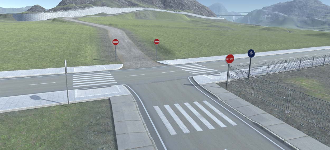
Introduced in beta 10. MultipleTraffic Sign prefabs can be assigned for each road type. Each prefab can be associated with a specific Traffic sign type, for example traffic signals or stop signs. The presets assigned to road types will be auto generated on Flex Connector connections when that road type is involved. Traffic signs can be added, edited and removed per connection.
It is possible to set the position of the traffic sign relative to the left, right side of the road or the center of the road. Offset options are available both in sideways and forward direction. It is also possible to set the type of traffic sign post. This can be useful at runtime for traffic light control scripts. And it can be used for auto placement of posts based on general rules and traffic sign post rules set per road type. For example "One Way" and "One Way - No Entry" traffic signals will be auto generated on one-way road objects.
The full list of traffic sign presets for a specific road type can be copied to other road types that will use similar traffic signs. To do so, press the "Copy" button, select the other road type, open the Traffic Signs foldout and press the "Paste" button.
Optionally the default settings for each prefab can be set by assigning the script component ERTrafficPost component to each individual prefab in the project folder. That way the default values only have to be set once. As soon as a traffic sign preset is activated for a road type or on a Flex Connector connection, the default prefab values will be inherited for this instance from the ERTrafficPost component.
The beta package demo scene includes three prefab examples. More traffic sign presets and material options will follow.
V3.3 includes options to create lane data for both roads and intersection accessible through the scripting API.
A new section AI Traffic is added to General Settings (6.21 in video). AI Traffic can be activated here, left-right-hand traffic can be set and you can specific how lane data should be generated on crossings.
Based on the new lane info options for road types, mentioned above, lane data will be generated automatically for roads. The display of the Lane data can be controlled in General Settings > Scene View > Display Lane Data (6.34 in video) or through Ctrl + L.
For intersections it is possible to auto generate lane connectors for all possible combinations (6.42 in video). Lanes can be selected, This shows a number of options. Relevant at this moment are Speed Limit and Delete Lane Connector. The other options will be activated later and more options will follow. Lanes can also be created manually (6.55 in video).
The Lane Data is avaialable through the scripting API. The simple road network in the scene "AI Traffic Scene" in the beta package is based on both the standard X crossing and the new Flex Connector and includes a basic AI script using the lane data. It is the same script as used in this video starting at 7.26.
Because Custom Connections based on your own meshes can be more complex, lane data for this type of connection objects can be set in the Unity Prefab editor by selecting the generated prefab in the project folder: /Assets/EasyRoads3D/Resources/custom prefabs/, and press "Open Prefab" in the Inspector. Select the "AI Lane Data" tab. Connection start and end points will be displayed based on the assigned road type. New lane connectors can be created by dragging from the start point (the small rectangle) to an end point of another connector. After creating a new lane connector, the number of Control Points can be adjusted and each control point can be selected and moved to define the desired curve for this lane connector.
The below video shows and example how a custom road shape can be created and how they are supported by the v3.3 Flex Connector.
Notes:
Limitations:
Known Issues / To Do:
V3.3 Road Map:
