Demo

Road shapes can be changed per marker in v3.
The shape of a road is defined by node positions. The default road only has two nodes, one on the left and one on the right. This will be customizable in v3.x and the custom connection system already make more complex roads possible.
The N key toggles the road shape changes feature on/off. When switched on you will see handles at the node positions. Multiple nodes can be selected by holding the Shift key when selecting nodes. Nodes can be updated on multiple markers at once by first selecting these markers, this is also done by holding the Shift key.
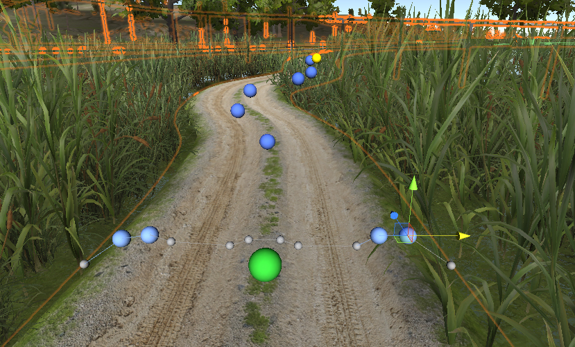
In the above example 5 markers (highlighted with green handles) are selected and 4 nodes are selected (highlighted in blue). Moving the position gizmo up or down witll update all selected nodes on all 5 markers.

This dirt path is a more advanced road type attached to two standard dirt paths, the ("Dirt Track Grass" road type, using the I Connector. I Connectors can be used to connect two different road types
The shape of the Dirt Path Swamp road type was generated through the Custom Prefab Editor window. We first created a simple plane model in a modelling app with the left and right tire track positions defined in the geometry. The object itself is.flat which makes it nicely connect with the other two dirt track segments through the mentioned I Connector.
The model was imported in the Custom Prefab Editor window, we added a connection and created a new road type matching the connection settings. Since we do not need the connection prefab itself it was afterwards removed from /Assets/EasyRoads3D/Resources/custom prefabs/
After creating the road in the scene and connecting it to both I Connectors we selected markers 1 to 7 by holding the Shift key. The N key toggles on road shape changes, and the nodes we want to raise were selected, also by holding the Shift key. The nodes can now be moved both in Scene View and in the Inspector further below in the marker settings. Moving the nodes a little bit up creates the tire shape as seen in the above screenshot. To finish it we selected individual markers to add some variation to the tire track shapes.
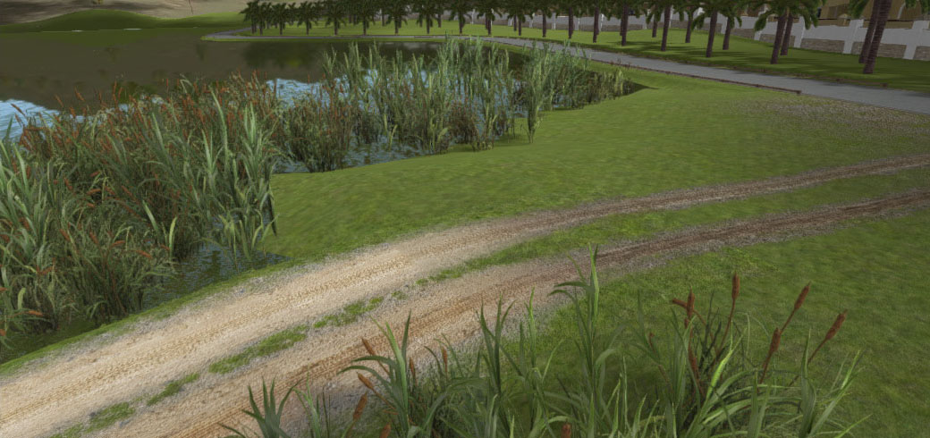
Since we didn't select the first and last marker the track itself still connects nicely with the other two dirt sections through the I Connector.
Note: v3.2 (in beta) includes built-in support for custom road shapes, this simplifies the process of creating the advanced shape
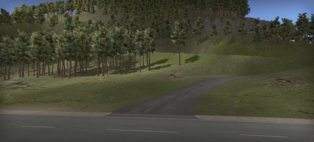
Here we have a crossing between the primary coastal road and the mountain road. We wanted the connection with the mountain road a little bit wider then the default width of the mountain road.
When connecting a road to a crossing with a different width the road stretches on the last triangle strip connecting to the crossing.

In this case the stretching is too much, it doesn't look like we want.
So we selected the last marker (the one that connects with the crossing) pressed the N Key to toggle on road shape changes and moved the left and right handles (the white handles in the above thumbnail) to the positions matching the left and right edge of the connection. The road width now smoothly adjusts over the last marker segments as you can see in the main screenshot above.
This is a process that will be automated in a further update. For now you can use the above method.
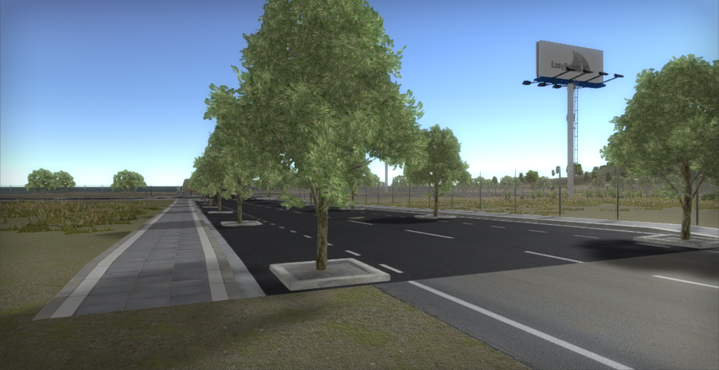
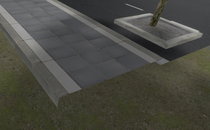
This will however leave a gap for the sidewalks. For the purposes of showing how to change the shape of objects we decided to simply adjust the sidewalk shape and level it with the ground instead of using an transition custom connection.
The N key activates node position changes. All nodes were selected (select one node and hit the S key), the y value was set to 0 in the Inspector which instantly updates all selected nodes.
By default the height of the sidewalks will gradually decrease from the previous marker to the selected marker. In this case the height change should occur over a smaller distance. This was achieved by using 1 for both the Min and Max "Ease In" values. ). The default Min value is 0. 0..1 means the change is adjusted over the full marker segment.
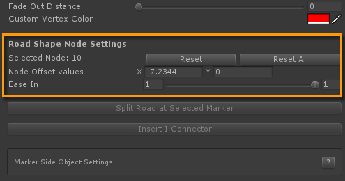
Min 1 Max 1 means that the change takes place at the very end over the last set of triangles only.

